
Pillar Slim — installation manual
Article contents
Installation guide for the original Pillar Slim configuration. Images, wiring and initial setup describe the station's original construction and local SmartSystem interface. Use the documentation supplied with your model. This text is not a universal guide for all current TouchPoint variants.
Installation, maintenance and repairs must be performed by a qualified electrician. An electrical inspection technician must check the installation. This manual preserves the original equipment's installation steps and safety instructions.
Routine operation of the original variant: Pillar Slim — operating instructions. Current variants and product sheets: Pillar Slim.
1. Introduction
This manual guides installation of the AgeVolt Pillar Slim charging station. It covers positioning, wiring and initial startup. Every installation step must be correctly followed and performed by a qualified electrician. An electrical inspection technician must check the installation.
1.1 General information
- Read all instructions before installing this product.
- Only a qualified electrician may install, repair or maintain the charging station. Unauthorized repair or modification immediately voids the warranty.
- Unauthorized modifications or conversions are prohibited.
- Do not install or use the charging station near flammable or explosive materials, chemicals or vapours.
- Do not operate the charging station outside its operating temperature range.
- Connect the charging station to the earthing system, as specified by the site's charging system design.
- Protect the charging station from impacts.
- The charging station has no built-in power switch. Always follow rules and regulations applicable to the local electrical installation.
- Incorrect installation could damage the charging station or the connected electric vehicle.
- An electrical inspection technician must inspect Pillar Slim after installation.
This manual contains notes and safety warnings about potential hazards. The symbols have the following meanings:
 DANGER — indicates an immediately hazardous situation that may cause death or serious injury unless appropriate measures are taken.
 CAUTION — indicates that property damage may occur unless appropriate safety measures are taken.
2. Charging station description
2.1 Socket version
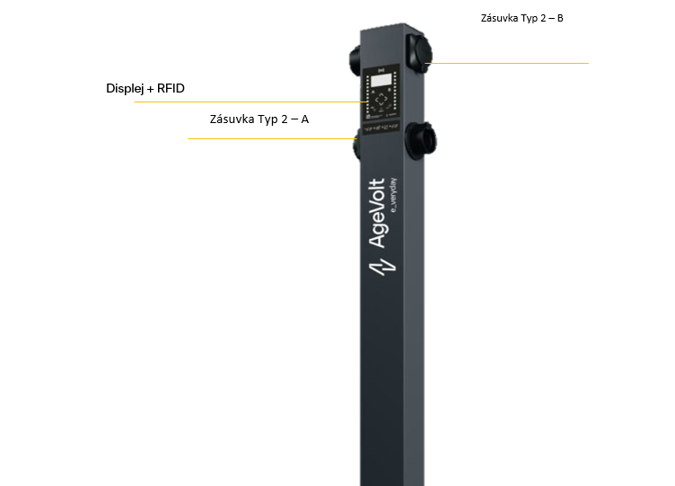
- Pillar Slim has two charging points (EVSE), A and B.
- Pillar Slim may have cable-equipped charging points instead of sockets.
- Pillar Slim may be supplied without a display and RFID reader. Their presence depends on the station configuration.
2.1 Description of selected charging station components
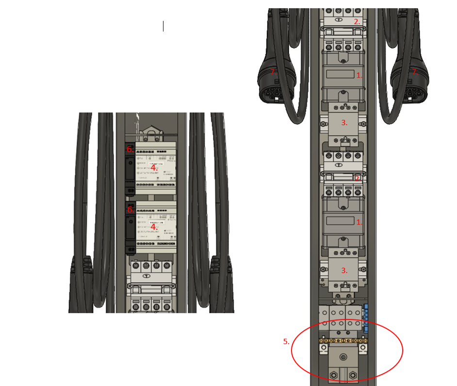
The image below identifies internal charger components in the socket configuration.
1. Electricity meter
2. Residual-current circuit breaker with overcurrent protection (RCBO)
3. Contactor
4. EV module (communications unit)
5. Input terminals for incoming power conductors and communication bus conductors
6. Power supply
7. Type 2 cable
3. Charging station specifications
3.1 Basic parameters
| Standard design | |
| Overall dimensions: 120x1475x100 mm | Weight: 15 kg |
| Number of charging points (EVSE): 2 | Operating temperature: -30°C to +50°C |
| Socket version: TYPE 2 Mennekes socket (IEC62196-2) | Operating humidity: 5% to 95% |
| Cable version: 5 m TYPE 2 Mennekes cable (IEC62196-2) | Storage temperature: -30°C to +60°C |
| Maximum EVSE power: 22kW | Surface material: Steel |
| Rated voltage: 3x400/230V AC, 24V DC | Internal access: Rear cover |
| Rated current: 63A | Protocol: OCPP-J 1.6 |
| Rated frequency: 50 z | Status indication: 2x LED strip |
| Ingress protection rating: IP54 | Electricity meter: MI class 1 |
| Mechanical impact resistance: IK10 | Protection: RCD DC 6 mA, RCBO AC Type A 30 mA |
| Optional accessories and components, which may not be included with the purchased station |
| SmartSystem |
|
Charging power regulation with SmartMeter only — dynamic control based on available building capacity |
| Wired internet connection: 10/100 BaseTX (TCPIP) — Ethernet RJ45 |
| Wireless internet connection: LTE/3G, Wi-Fi |
| SmartMeter — requires SmartSystem |
| Current sensors and electricity meters — building consumption monitoring (50–2400 A) |
| Display with RFID card reader — requires SmartSystem |
| Information display: 2-line LCD and touch buttons |
| RFID reader: 13.56 MHz (ISO14443A) |
| Wireless connection — requires SmartSystem |
| 4G/3G network connection |
4. Planning installation
Installing a Pillar Slim charging station requires:
- Calculating the existing electrical load to determine maximum operating current.
- Calculating cable distances to ensure minimal voltage drop.
- Obtaining required local authority permits, such as a building permit.
- Arranging a subsequent electrical inspection of the installation.
- Conductors must be sized in accordance with local standards.
- Cable insulation must comply with local standards.
Before installation, discuss all electrical equipment, including residual-current protection, overcurrent protection and wiring, with a certified electrician.
For maximum charging power, use a three-phase circuit breaker rated at 63 A. Where this current is unavailable, adjust the maximum available charging current in the station settings too.
4.1 Power cable requirements
-
- For looped cabling
-
- Max AYKY 2x4x50mm² TN-C, CYKY-J 2x5x25mm² TN-S.
- Protect the loop at a maximum of 100 A, or 80 A for a long route. Where voltage-drop compensation is required, reduce the protection rating rather than increasing conductor cross-section.
- Length: at least 60 cm above ground level.
-
- For connecting only one charger
-
- CYKY-J 5x16mm² with 63 A protection
- Length: at least 60 cm above ground level.
-
- For lightning protection
-
- 8 mm aluminium round conductor. Disconnected from the earthing strip, with corrosion protection at the joint.
- At least 0.5 m above ground level
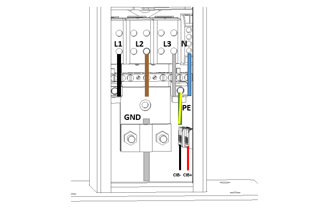
Maintain the correct phase sequence L1, L2, L3 (U, V, W) at the station input!
4.2 Communication and data cable requirements
1. Communication bus
- The CIB bus communicates between chargers and SmartSystem, so every charger must be connected.
- Star and bus topologies may be combined, but ring topology is not permitted.
- The maximum cumulative length of one bus branch is 300 m.
- Possible cable types:
- Black outdoor double-sheath CAT5E FTP
- J-Y(St)Y 2x2x0.8 — must be used with outdoor conduit
- A-2YF(L)2Y 2x2x0.8
2. Network/internet connections
Only where the station is a Master containing SmartSystem and LTE or Wi-Fi is not used.
-
- CAT6A cabling terminated with a keystone in the station. At least 1 m above ground level.
- Maximum distance from the active network device is 100 m.
4.3 Space requirements
We recommend placing Pillar Slim on SmartBase for an underground chamber or SolidBase for a concrete foundation or solid surface, near the parking space. Account for cable length and convenient station access throughout charging. Do not place Pillar Slim on an unstable or flammable surface or near heat sources. Pillar Slim is approved for outdoor installation without additional weather protection.
Follow local electrical installation, fire protection and accident prevention regulations, and maintain escape routes at the site. Do not install where falling objects could damage the station.
Recommendations:
- Consider charging cable length when positioning the station. Park the electric vehicle with its charging port within cable reach. Maintain sufficient space between vehicle and station throughout charging for easy access to both charging points.
5. Installation
5.1 Installation tools and materials

5.2 Installation on SolidBase/SmartBase
Warning: before installation, switch off the incoming cable's circuit breaker and verify absence of voltage.
Prerequisite:
— Installed SolidBase/SmartBase; see its installation manual
Required accessories:
- 4x M8x30 bolt set
- 4x M8 polyamide washers
- 4x M8 protective bolt-head caps
- Rubber sealing gasket
Installation steps.
1. Remove the station's upper and rear covers

2. Place the sealing gasket on SolidBase/SmartBase
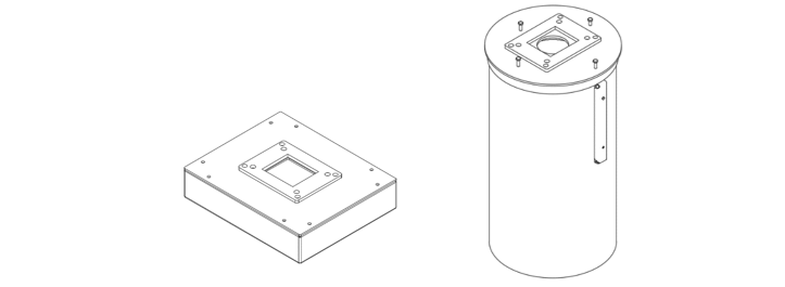
3. Feed cables from SolidBase/SmartBase through the gasket and station bottom. Position the station so the holes in its bottom plate align with those in SolidBase/SmartBase.
4. Secure the station with four M8x30 bolts and polyamide washers.
5. Fit the bolt-head caps
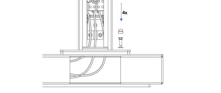
6. Connect station cables; see section 5.3
7. Close the station's rear cover
8. Fit the station's upper cover
5.3 Connecting cables
Warning: before installation, switch off the incoming cable's circuit breaker and verify that the cable is not live.
5.3.1 Connecting power conductors and CIB communication conductors
5.3.2 Ethernet connection
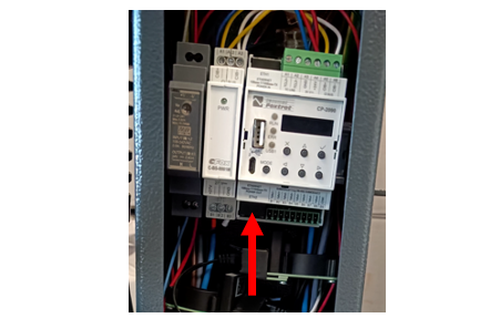
If Pillar Slim contains SmartSystem, connect the prepared Ethernet cable to ETH2 at the bottom.
6. Commissioning the charging station
Before switching on the incoming cable's circuit breaker, use a multimeter to check for short circuits between conductors.
6.1 Initial startup
Switch on the RCBO inside Pillar Slim and close the rear panel. Switch on the switch/circuit breaker in the distribution board. If SmartSystem is outside the station, switch on its power too. Pillar Slim starts. On first startup, factory defaults apply; adjust charging power to the available capacity of the upstream circuit breaker.
7. Troubleshooting
7.1 Possible problems and solutions
| Status | Error | Solution |
| The charging station did not start or is not working correctly |
The input phase sequence L1, L2, L3 (U, V, W) is incorrect |
Check the phase sequence |
|
Input conductors are not correctly fitted in the terminals |
Check conductor fastening and tighten connections | |
|
The display shows: Circuit breaker error |
The station's residual-current device/circuit breaker has tripped |
Check the residual-current device/circuit breaker inside the station |
|
The display does not work although the station's circuit breaker is on |
SmartSystem fault. |
Check SmartSystem power and correct operation |
|
The display shows HALT |
The system is updating |
Wait for the update to finish |
|
|
The station is incorrectly configured in SmartSystem. The display address differs from the configured address |
Adjust the SmartSystem configuration |
7.2 Restarting the charging station
Disconnecting and reconnecting power restarts the station. If the control unit is in the building's distribution board, switching its upstream circuit breaker off and on is sufficient.
8. Maintenance, repairs and care
8.1 Maintenance
The charging station requires minimal maintenance. AgeVolt recommends regular electrical inspections by authorized, qualified personnel according to local requirements. Owners should perform regular visual checks and keep the station in good operating condition to prevent damage, faults or accidents.
8.2 Repairs
Unauthorized charging station repairs are prohibited. Repairs must be performed only by a qualified electrician using original AgeVolt-approved replacement parts.
8.3 Cleaning
If required, clean the charging station only with a dry cloth. Disconnect power while cleaning to avoid electric shock. Do not use a pressure washer or aggressive cleaning agents.
Text © AgeVolt Slovakia, s. r. o. 2024
Image © AgeVolt Slovakia, s. r. o. 2024
This manual is protected by copyright. Use without the creator's consent is prohibited. Copying, including partial copying, requires their permission.