
Connecting T2 output cables to the Wallbox Double charging station
Article contents
The technical section is intended for a qualified professional. Sizing examples do not replace a site-specific design or the supplied equipment's documentation.
Package contents
- a fully enclosed Wallbox Double charging station,
- separately packaged output cables,
- covers, screws and nuts required for installation.
Output cables are supplied detached to simplify installation and prevent transport damage.
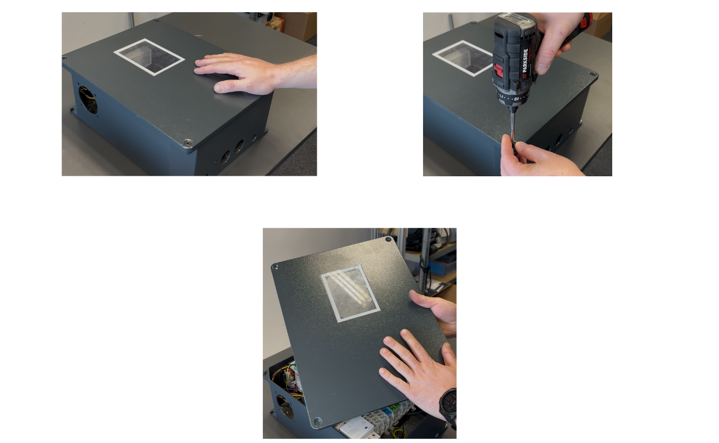
1. Opening the charger
- Undo four cover screws using a manual screwdriver or driver.
- Use suitable tools: a PH2 screwdriver/bit and security screw bit. Avoid worn or undersized tips.
- Remove the cover. If it has a sticker, set it aside without damaging it, for example against a sharp object.
 2. Preparing materials
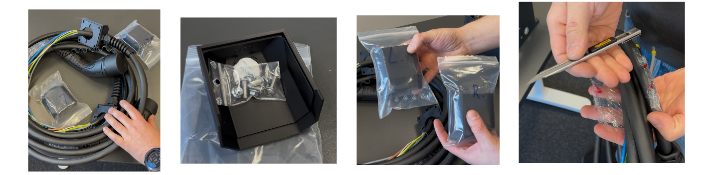
- Sort cables and covers labelled L, left, and R, right.
- Each cover contains an NFC tag paired with its EV module. Do not swap them.
- Conductors are cut to precise lengths.
- Prepare the fasteners:
- screws: M5x16 stainless steel, flanged, charging
- nuts: M5 flanged with locking serrations.
Carefully release cables if bundled with a tie. When using a knife, avoid damaging cable insulation.
3. Installing the cable in the charger
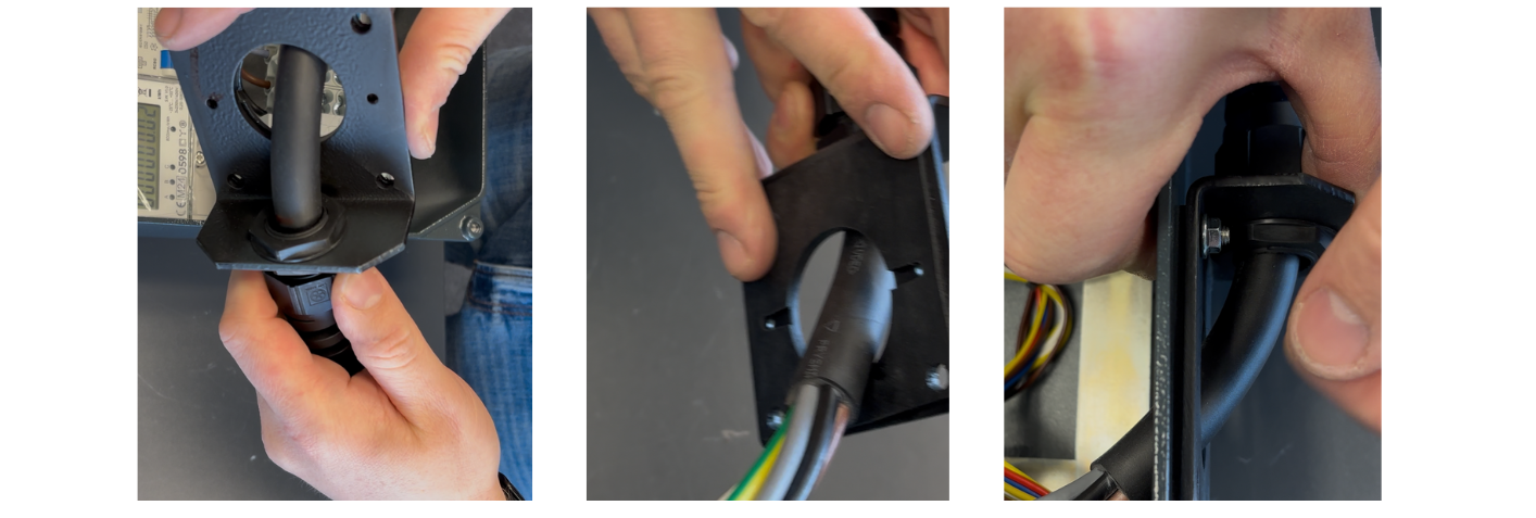
- Check that the metal gland contains its seal to ensure watertightness.
- Feed the cable through the charger opening.
- Fit screws from inside outward, initially by hand and gently; do not tighten fully.
4. Connecting conductors — left side (L)
Connection order:
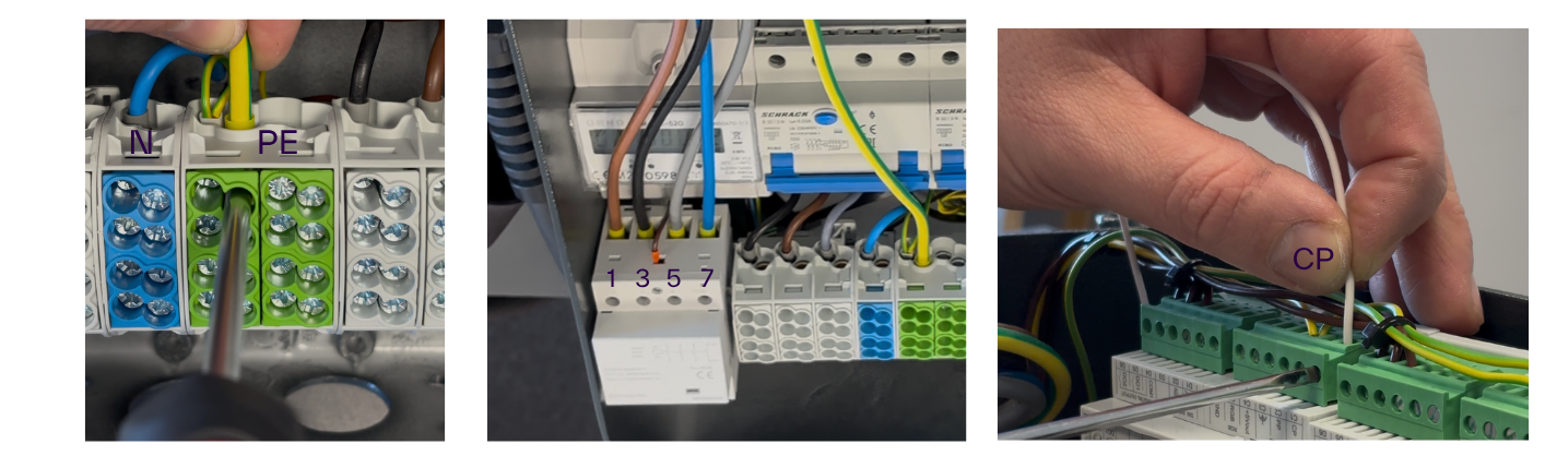
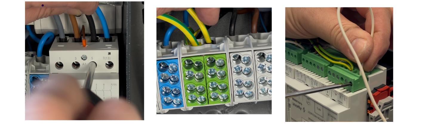
- Protective earth (PE) — connect to the green incoming terminal. The ferrule's insulated part must remain visible. Check fastening by pulling the conductor.
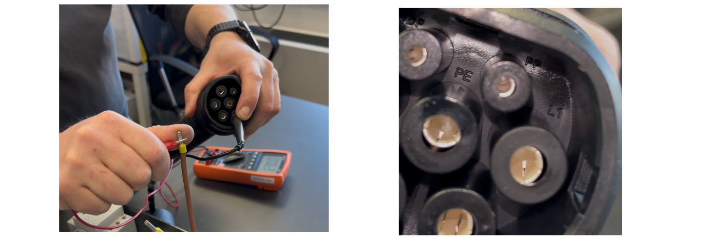
- Phases — if individual phases are not labelled, such as L1 brown, L2 black and L3 grey, you must verify colour-to-connector-position assignments using a multimeter:
L1, phase 1 — position 1 on the left contactor, brown conductor; L1 is brown in this cable,
L2, phase 2 — position 3 on the left contactor, black conductor,
L3, phase 3 — position 5 on the left contactor, grey conductor,
N, neutral — position 7.
- Bundle the cables with a cable tie and route them alongside the circuit breaker so that the meter display remains readable and the cables do not prevent the moving parts of the circuit breaker from moving.
- CP conductor (communication with the EV) — connect it to position C1 on the left EV module (also marked CP). Check that the stripped section does not protrude. Tighten with a 3.5 mm flat-head screwdriver.
Positioning the bundled cables

Checking the colours assigned to the connector positions with a multimeter
5. Fitting the cover — left side
- Each cover has an NFC tag containing the EV module's serial number. The covers must not be swapped.
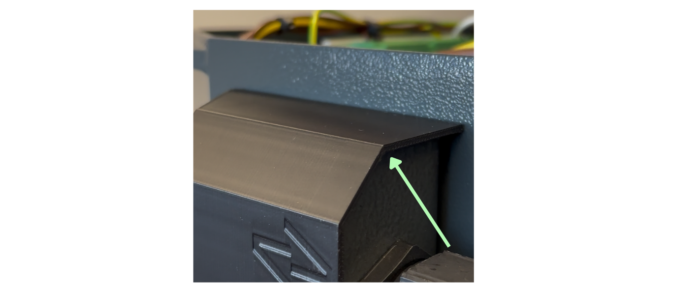
- Slide the cover on parallel to the sheet metal, rather than at an angle.
- Push it in until it protrudes slightly below the sheet metal.
- Tighten the four screws evenly using a hex bit in a small ratchet or a 3 mm ball-end hex screwdriver.
- The serrated nuts hold themselves in place; you do not need to hold them with a spanner.
- In hard-to-reach places, you can use a ball-end hex screwdriver.
6. Wiring — right side (R) with phase rotation
- A separate cover with an NFC tag and a second cable are provided.
- When unwrapping the cables, take care not to damage the insulation.
Connecting the conductors:
- Pass the cable through the opening and tighten the screws lightly. Do not fully tighten them, to avoid turning the nuts.
- Protective earth conductor (PE) — connect it to the terminal block; the insulated part of the ferrule must remain visible. Check the connection by pulling gently.
- N conductor — position 7 on the right contactor.
- Phases (we rotate the phases on the right port so that the first phase is not loaded more heavily than the others :
- L3 (phase 3) position 1 on the right contactor — grey conductor,
- L1 (phase 1) position 3 on the right contactor — brown conductor for this cable,
- L2 (phase 2) position 5 on the right contactor — black conductor.
- Bundle the cables with a cable tie and route them alongside the circuit breaker so that the display remains readable and the cables do not obstruct the circuit breaker's movement.
- CP conductor (communication with the EV) — connect it to position C1 on the right EV module (also marked CP). Check that the stripped section does not protrude. Tighten with a 3.5 mm flat-head screwdriver.
7. Fitting the cover — right side
- Each cover has an NFC tag containing the EV module's serial number. The covers must not be swapped.
- Slide the cover on parallel to the sheet metal, rather than at an angle.
- Push it in until it protrudes slightly below the sheet metal.
- Tighten the four screws evenly using a hex bit in a small ratchet or a 3 mm ball-end hex screwdriver.
- The serrated nuts hold themselves in place; you do not need to hold them with a spanner.
- In hard-to-reach places, you can use a ball-end hex screwdriver.