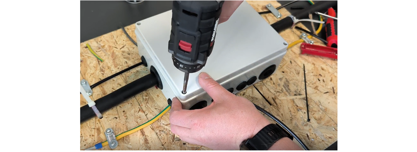
Junction box installation guide
Article contents
The technical section is intended for a qualified professional. Sizing examples do not replace a site-specific design or the supplied equipment's documentation.
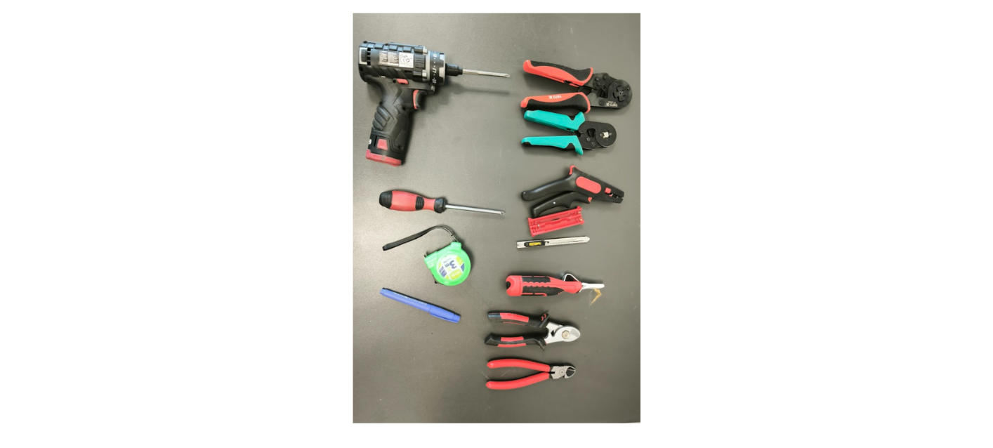
Tool list
- a sharp utility knife with a non-plastic body
- a Jokari cable-stripping knife
- side cutters
- cutters for larger conductor cross-sections
- a stripping tool for larger conductor cross-sections
- wire strippers
- ferrule crimping pliers
- ferrule crimping pliers for 16 mm² and larger
- a cordless driver with a long PZ2 bit
- a PZ2 screwdriver
- a tape measure/ruler
- a marker
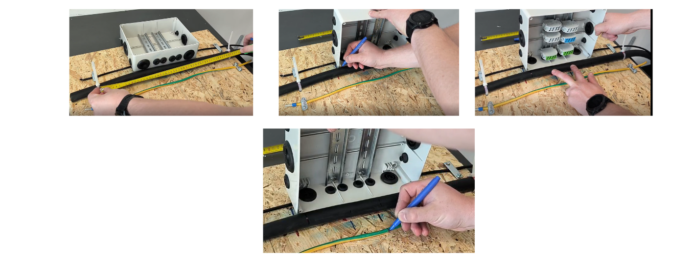
1. Preparation and measurement:
- We have only ONE attempt at cutting, because this is a continuous cable branch with no spare length.
- Do not begin by cutting. First measure the box position accurately.
- Cable clamp spacing is fixed at 500 mm.
- The box's external dimension is 245 mm. Part of the cable's outer insulation must enter the box, rather than only the stripped conductors.
- Position the box midway between cable clamps, leaving 125 mm on each side from the wall-mounted cable clamp edge to the box edge.
- Measure everything several times, as there is only ONE attempt.
- Mark the box edges on the wall or ceiling to show where the cable glands will end.
- Mark where to expose the incoming cable conductors and mark the DIN rail centrelines, where individual conductors will later be cut. Cut the protective earth conductor on the DIN rail centreline too, not at the box centre.
2. Stripping the cable:
- Use a conventional Jokari knife or a very sharp small utility knife with a non-plastic body.
- Remove the outer insulation gradually and carefully without damaging the inner conductors. Cutting a conductor would require replacing the entire incoming cable.
- The cable is already fixed to the wall and has no spare length, so a Jokari knife will probably not reach around the full circumference. A thin, sharp utility knife is therefore more suitable.
- Pliers can help remove sections of outer insulation that cannot be cut cleanly.
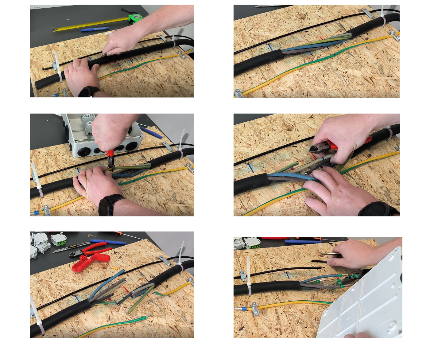
3. Preparing conductors:
- After stripping, individual conductors should be clean and undamaged.
- Check individual conductors and shorten them to the required length. Confirm by positioning the box again or measuring the necessary distances.
- Mark and cut conductors individually, not all at once.
- Remove the central cable support element if present.
- Maintain the colour sequence where possible and arrange conductors neatly side by side. Gently twisting them may help.
- Now cut the protective earth conductor too.
4. Preparing terminal blocks:
- The terminal blocks have been kept outside the box to avoid obstruction.
- Strip the ends of separated conductors and crimp ferrules to ensure firm, reliable terminal block connections.
- Strip only enough for the conductor to reach the ferrule stop without extending beyond its insulated collar. Strands must not end halfway inside the ferrule or protrude from it.
- Now cut the data cable as well.
5. Cable glands and inserting conductors:
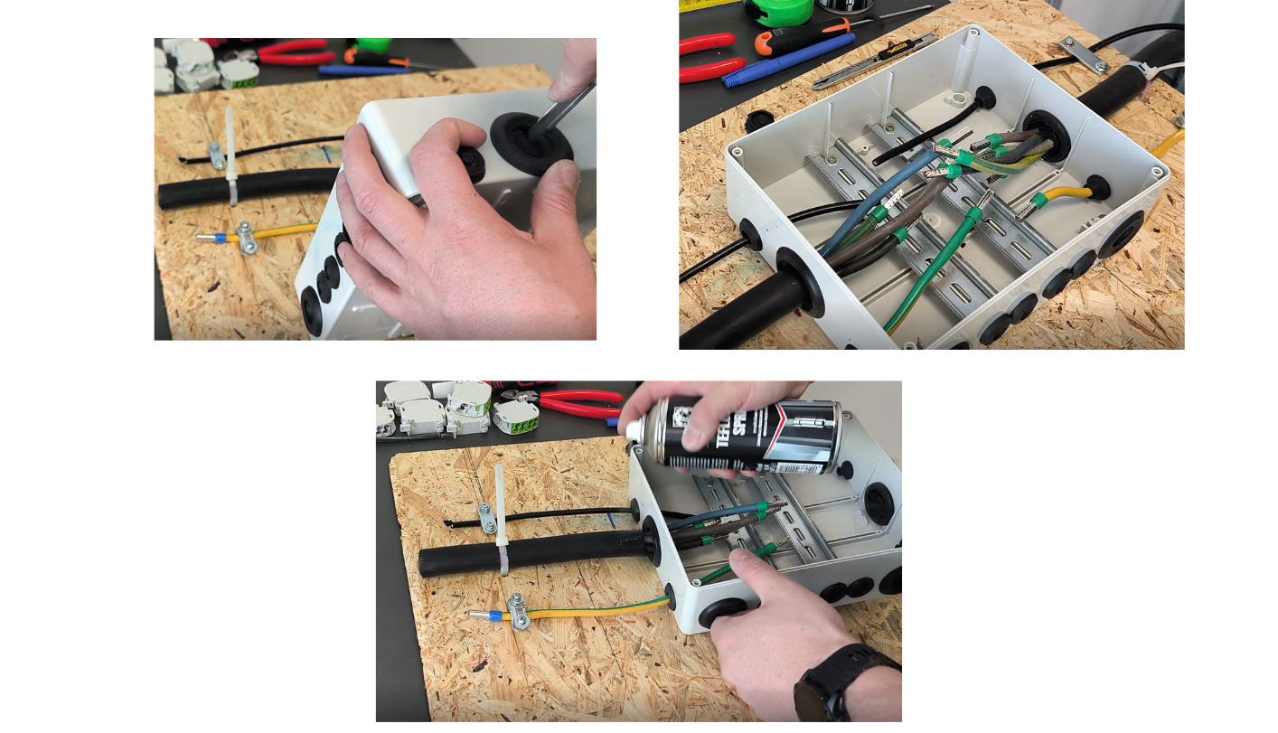
- Cut openings in the box glands.
- Push the data and earth cables through 16 mm glands; piercing them is sufficient.
- Use a 40 mm gland for the power cable and cut only enough to push it through while maintaining the seal. Position the opening as close as possible to the box's lower wall to minimize cable bending.
- Use dry PTFE spray or powder to help push part of the outer insulation through the gland.
- Repeat on the other side if required, for a Wallbox Double or two Wallbox One units.
6. Securing the box and connecting conductors:
- If measurements are correct, the outer insulation enters the box slightly from both sides without occupying working space.
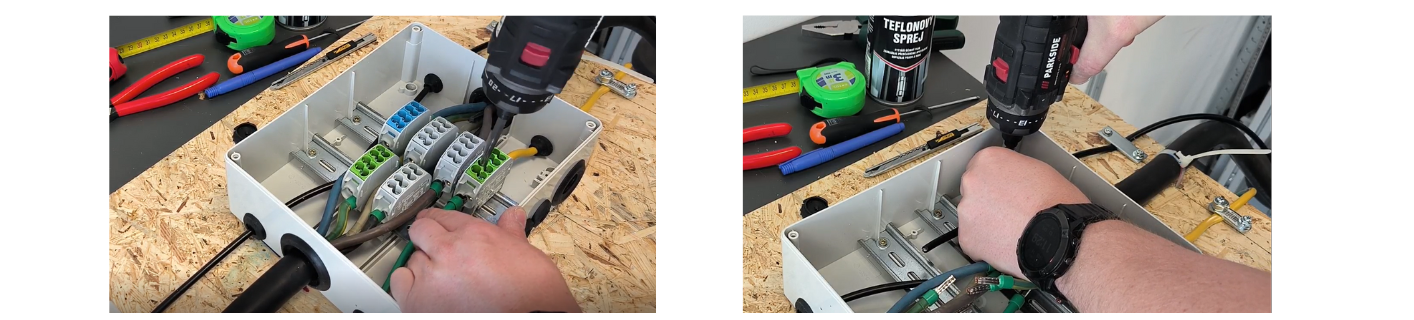
- Secure the box to the supporting material.
- Start by connecting the protective earth conductor so it does not obstruct later work.
- Continue with the remaining conductors, arranging them with minimal crossing. Avoid putting them all in one row while keeping crossings to a minimum.
- After inserting each conductor, tighten its terminal. Arrange them according to their actual sequence rather than the drawing order to minimize crossing.
7. Data cable:
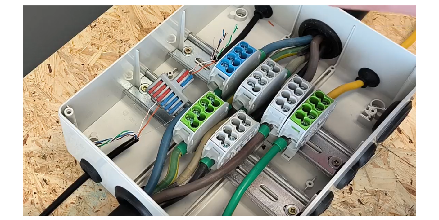
- Strip 4–5 cm of outer insulation, not just the end.
- Then strip the individual conductors.
- Connect conductors using Wago terminals or equivalent and check polarity.
- Verify the connection by gently pulling each conductor.
8. Branch cable to the charger:
- Use a 5 × 6 mm² cable, which is thinner and easier to work with.
- Strip a suitable length, for example the box length.
- Check the knife setting so the cut does not damage conductors.
- Remove the reinforcement element or cord from the cable centre.
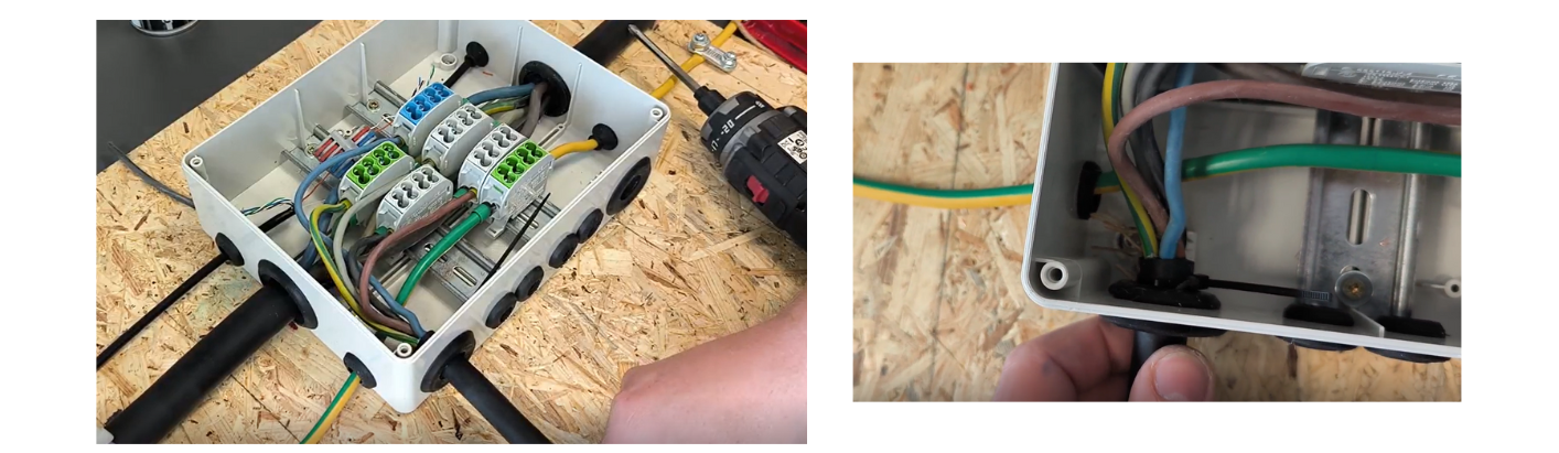
- Enter the box through the lower-left gland.
- Make a small cut and push the conductors through, using PTFE spray to assist.
- Secure the cable with a cable tie so it cannot slip out of the box.
- Trim conductors and route them to individual terminal blocks without excessive tension or excessive spare length that would obstruct the box.
- Strip, crimp a ferrule and connect the conductor to the terminal block.
- Ensure the ferrule is seated against the conductor insulation.
9. Protective earth conductor:
- Use a 16 mm gland, piercing it only.
- The conductor must not be taut. Shorten it to approximately the terminal block centre.
- Strip, crimp a ferrule and insert it fully into the terminal block, ensuring the ferrule's insulated collar overlaps the conductor insulation.
- Tighten carefully.
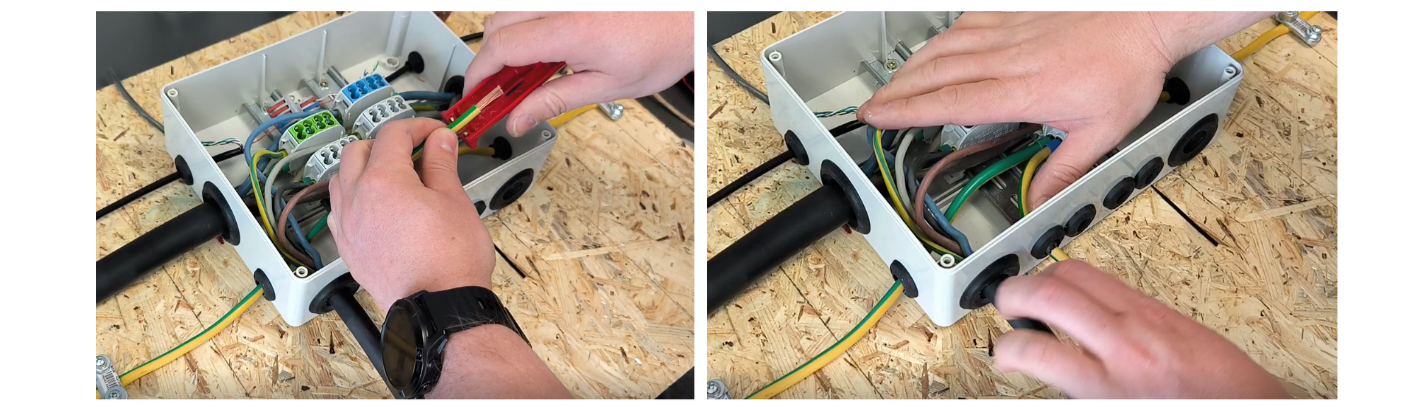
10. Data cable to the charger:
- Enter through a pierced 16 mm gland.
- Shorten the cable if required. Strip 5–10 cm.
- Maintain the same colour sequence as before.
- Fold and insulate unused conductors or cut them off.
- Strip active conductors and connect them to the terminal block.
- Secure the cable with a cable tie.
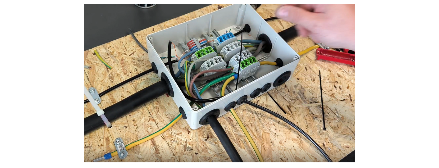
11. Closing the box:
- Before fitting the cover, check that no conductors protrude.
- The box must seat correctly in the cover's sealing groove.
- Tighten the manufacturer's supplied screws evenly and carefully.
- Do not tighten the first screw fully at once; progressively tighten all four.