
Wallbox One — installation manual
Article contents
Installation guide for the original Wallbox One configuration. Images, wiring and initial setup describe the station's original construction and local SmartSystem interface. Use the documentation supplied with your model. This text is not a universal guide for all current TouchPoint variants.
Installation, maintenance and repairs must be performed by a qualified electrician. An electrical inspection technician must check the installation. This manual preserves the original equipment's installation steps and safety instructions.
Routine operation of the original variant: Wallbox One — operating instructions. Current variants and product sheets: Wallboxes.
This manual guides installation of AgeVolt Wallbox One, also called the wallbox or station. It covers positioning, wiring and initial startup. Every installation step must be correctly followed and performed by a qualified electrician. An electrical inspection technician must check the installation.
This document contains important instructions and warnings for station installation and maintenance.
- Read all instructions before installing this product.
- Only a qualified electrician may install, repair or maintain the station. Unauthorized repair or modification immediately voids the warranty.
- Unauthorized modifications or conversions are prohibited.
- Do not install or use the charging station near flammable or explosive materials, chemicals or vapours.
- Do not operate the station outside its operating temperature range.
- Connect the station to the earthing system, as specified by the site's charging system design.
- Protect the charging station from impacts.
- The station has no built-in power switch. Always follow local electrical installation rules and regulations.
- Incorrect installation could damage the station or the connected electric vehicle.
- An electrical inspection technician must inspect Wallbox One after installation.
This manual contains notes and safety warnings about potential hazards. The symbols have the following meanings:
 DANGER — indicates an immediately hazardous situation that will cause death or serious injury unless appropriate measures are taken.
 CAUTION — indicates that property damage may occur unless appropriate safety measures are taken.
2. Charging station description
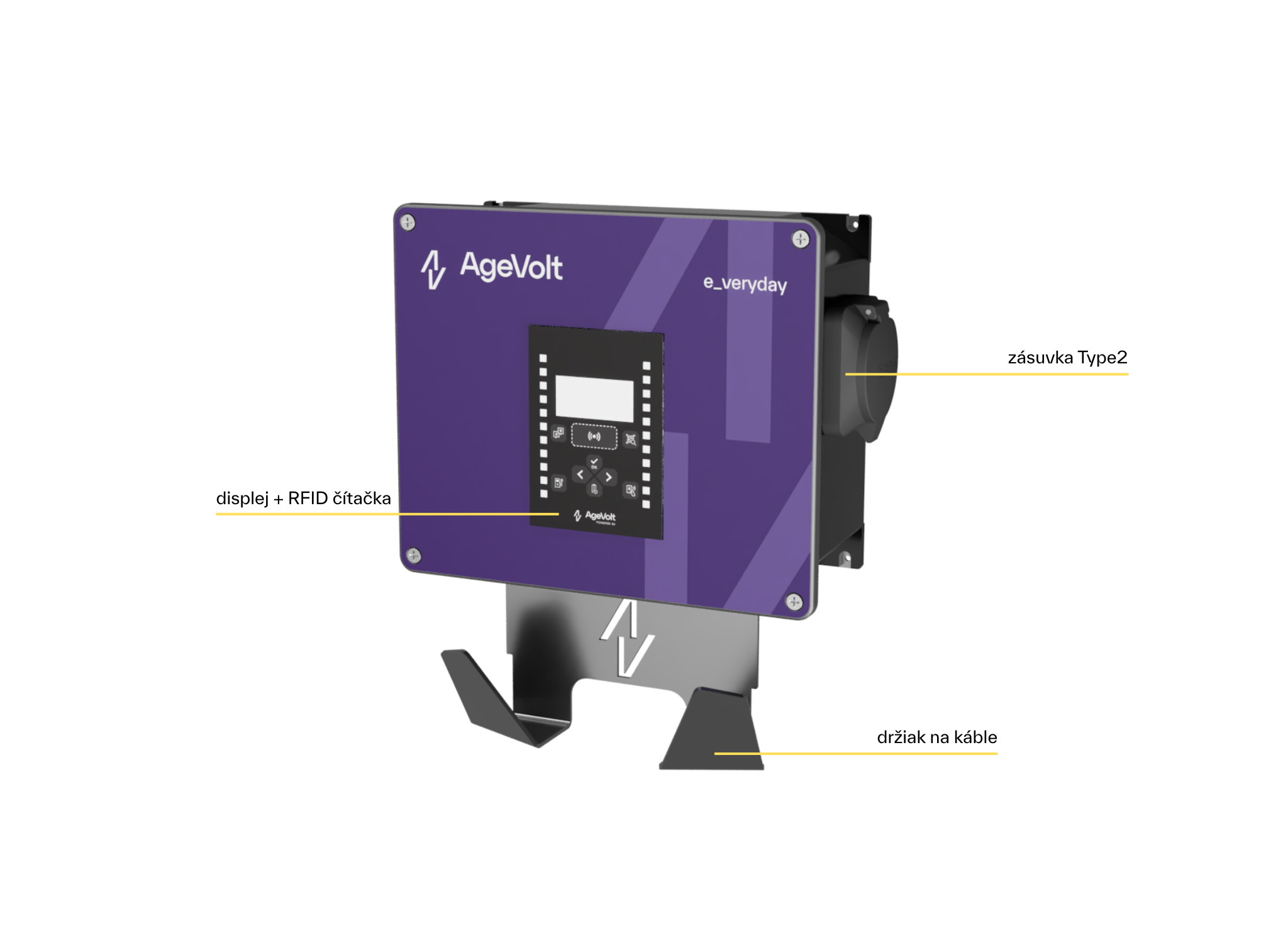
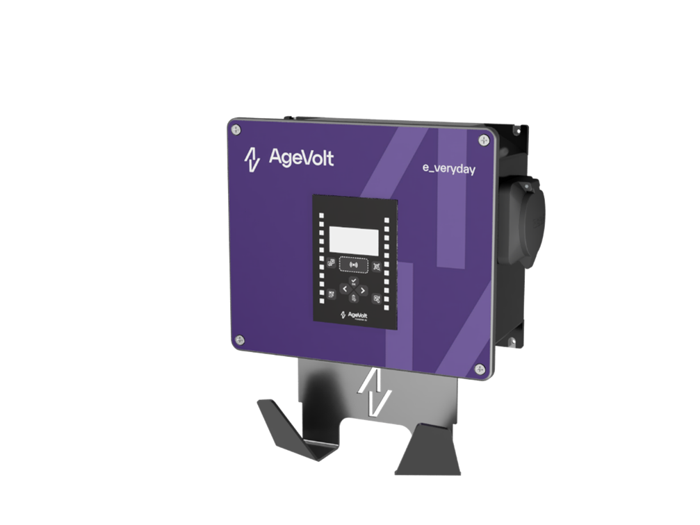
2.1 Station version with a socket
2.2 Station version with a cable
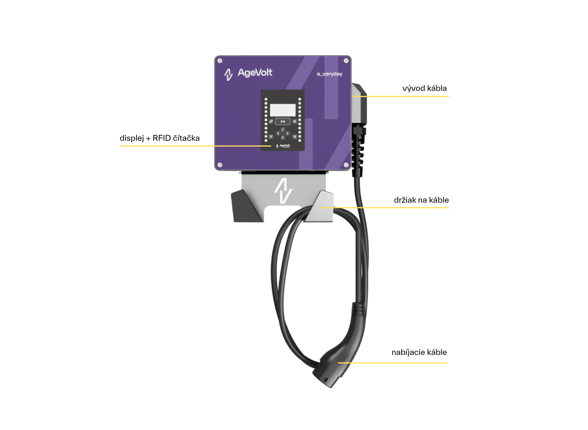
*A display with RFID reader may not be fitted. Display availability depends on station configuration.
2.3 Description of selected station components
The image below identifies the station's internal components.
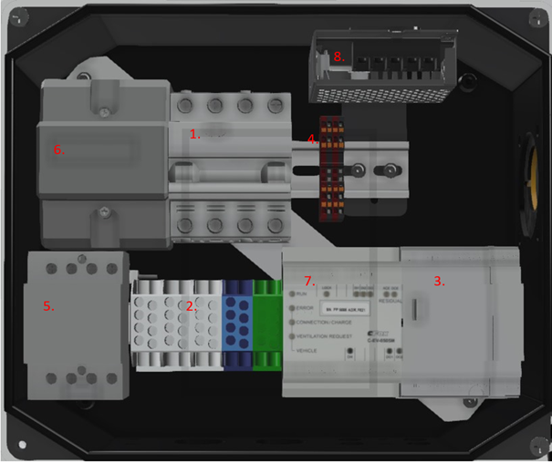
- Residual-current circuit breaker with overcurrent protection (RCBO) / miniature circuit breaker (MCB), depending on configuration
- Input terminals for incoming power conductors
- SmartSystem
- Input terminals for communication bus conductors
- Contactor
- Electricity meter
- EV module: communications unit
- Power supply
3. Charging station specifications
3.1 Basic parameters
Standard AgeVolt Wallbox One AC 1x22 kW version
| Overall dimensions: 314x264x125 mm | Weight: 8 kg |
| Number of charging points (EVSE): 1 | Operating temperature: -30°C to +60°C |
| Socket version: Type 2 Mennekes socket (IEC62196-2) | Storage temperature: -30°C to +60°C |
| Cable version: Type 2 Mennekes cable, 5 m (IEC62196-2) | Surface material: Aluminium alloy (AlMgSi) |
| Maximum power EVSE: 22 kW | Installation access: Front cover |
| Rated voltage: 3x400/230V AC, 24V DC | Electricity meter: MID class 1 |
| Rated current: 32A | DC protection: RCD DC 6 mA |
| Rated frequency: 50Hz | Surge protection (optional): B+C |
| Ingress protection rating: IP54 | Operating humidity: 5% to 95% |
| Mechanical impact resistance: IK10 |
4. Planning installation
Installing a Wallbox One charging station requires:
- Calculating the existing electrical load to determine maximum operating current.
- Calculating cable distances to ensure minimal voltage drop.
- Obtaining required local authority permits, such as a building permit.
- Arranging a subsequent electrical inspection of the installation.
- Conductors must be sized in accordance with local standards.
- Cable insulation must comply with local standards.
Before installation, discuss all electrical equipment, including residual-current protection, overcurrent protection and wiring, with a qualified electrician.
For maximum charging power, use a three-phase circuit breaker rated at 32 A. Where this current is unavailable, adjust the maximum available charging current in station settings accordingly.
4.1 Power cable requirements
Minimum, reduced charging power 1×11 kW:
- incoming CYKY-J 5 × 2.5 cable providing 400 V / 16 A at the Wallbox One location
- 16 A circuit breaker upstream of the station*
Optimal, full charging power 1 × 22 kW:
- incoming CYKY-J 5 × 6 cable providing 400 V / 32 A at the Wallbox One location
- 32 A circuit breaker upstream of the station*
*Supply cable parameters below this minimum may be installed following individual discussion with an AgeVolt technician, reducing the available charging output.
Vehicles have different onboard chargers and charging power. Although the station is rated at 22 kW, three-phase 32 A, the vehicle may charge more slowly depending on its onboard charger.
Maintain the correct phase sequence L1, L2, L3 (U, V, W) at the station input!
If no internal RCBO is fitted, ensure the incoming cable is already RCBO-protected in the building's distribution board!
4.2 Communication and data cable requirements
J-Y(ST)Y communication cable must connect the station to SmartSystem if external, and SmartSystem to SmartMeter in the distribution board. It must also be installed between multiple stations for communication. We recommend it even for a single station to simplify future expansion.
Optimal requirement: J-Y(ST)Y 2 × 2 × 0.8
FTP communication cable is required to connect the station to the local network/internet when SmartSystem is inside the station.
Optimal requirement: FTP CAT5e or higher + RJ45
Wallbox One can be wall-mounted or placed on a stand. We recommend a brick/concrete wall, a stand on a concrete foundation of at least 40x40x40, or SmartBase near the parking space, considering cable length and convenient access throughout charging. Do not mount it on an unstable or flammable wall, fence or pillar, or near heat sources. It is approved for outdoor installation without additional weather protection.
Follow local electrical installation, fire protection and accident prevention regulations, and maintain escape routes at the site. Do not install where falling objects could damage the station.
Recommendations:
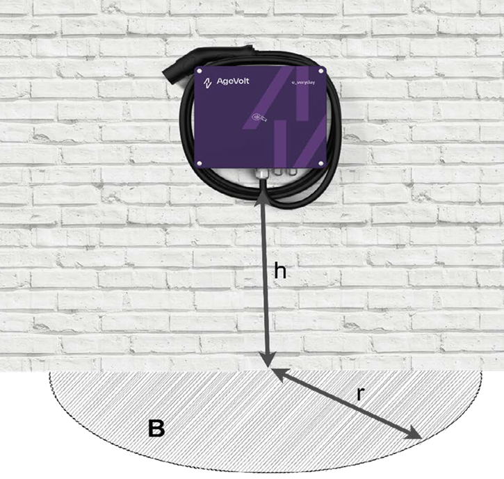
Height h = 1.2 m above ground
- Adjust height for convenient access if needed, always considering safe station access during EV charging.
Zone B, r = 3 m, depending on cable length
- Consider cable length when positioning the station. Park with the EV charging port in zone B, within cable reach. Maintain sufficient space between vehicle and station for easy access throughout charging.
5. Installation
5.1 Installation tools and materials
Before installing Wallbox One, prepare the following tools and materials:
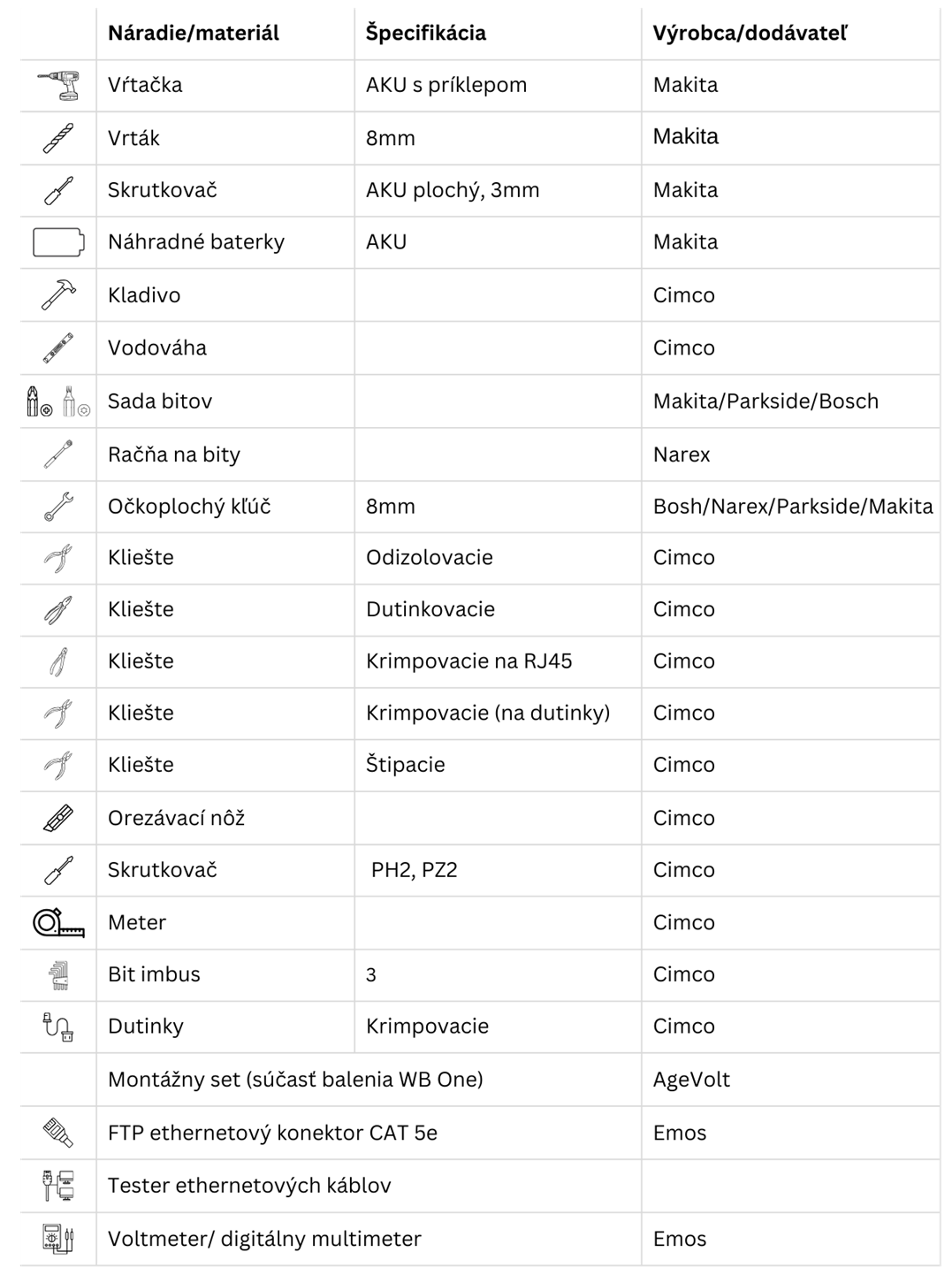
5.2 Preparing the installation area
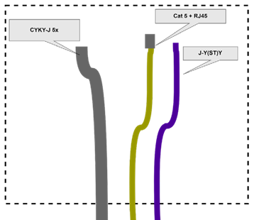
Run CYKY-J power cable to the solid wall or stand with sufficient length for the correct wallbox height plus 0.5 m for internal and subsequent connections. Prepare J-Y(ST)Y and CAT + RJ45 cables to the same length.
Future position on the Wallbox
5.3 Wall installation
Warning: before installation, switch off the incoming cable's circuit breaker and verify that the cable is not live.
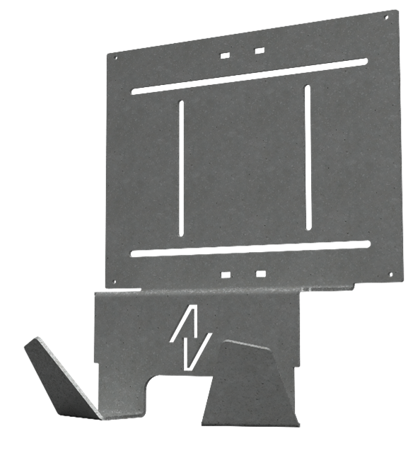
- Place the Wallbox One bracket at the recommended height; see section 4.3. Mark four suitable positions within its mounting openings.
- Drill four holes, Ø 8 mm and 70 mm deep.
- Insert wall plugs flush with the wall.
- Fit glands in the bracket's designated openings: 2x32, 4x16.
- Secure the bracket using the supplied screws.
- Place the wallbox on its bracket and secure the station corners with four M5x12 DIN6921 A2 screws.
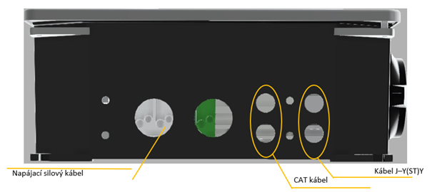
- Feed power and communication cables through the glands. For easier installation, feed them through before fitting the wallbox to the bracket. Use the designated separate gland for each cable.
5.4 Stand installation
Warning: before installation, switch off the incoming cable's circuit breaker and verify that the cable is not live.
- Fit glands in the bracket's designated openings: 2x32, 2x16.
- Feed power, communication and data cables through the bracket glands.
- Secure the bracket to the stand using the supplied screws.
- Place the wallbox on its bracket and secure the corners with four M5x16 screws.
5.5 Connecting cables
Warning: before installation, switch off the incoming cable's circuit breaker and verify that the cable is not live.
5.5.1 Connecting power conductors
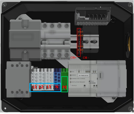
First connect PE to its terminal, then N, followed by L1, L2 and L3.
Connections must comply with local standards and be performed by a qualified electrician. An electrical inspection technician must inspect the entire installation afterwards.
5.5.2 Connecting CIB conductors
5.5.3 Ethernet connection
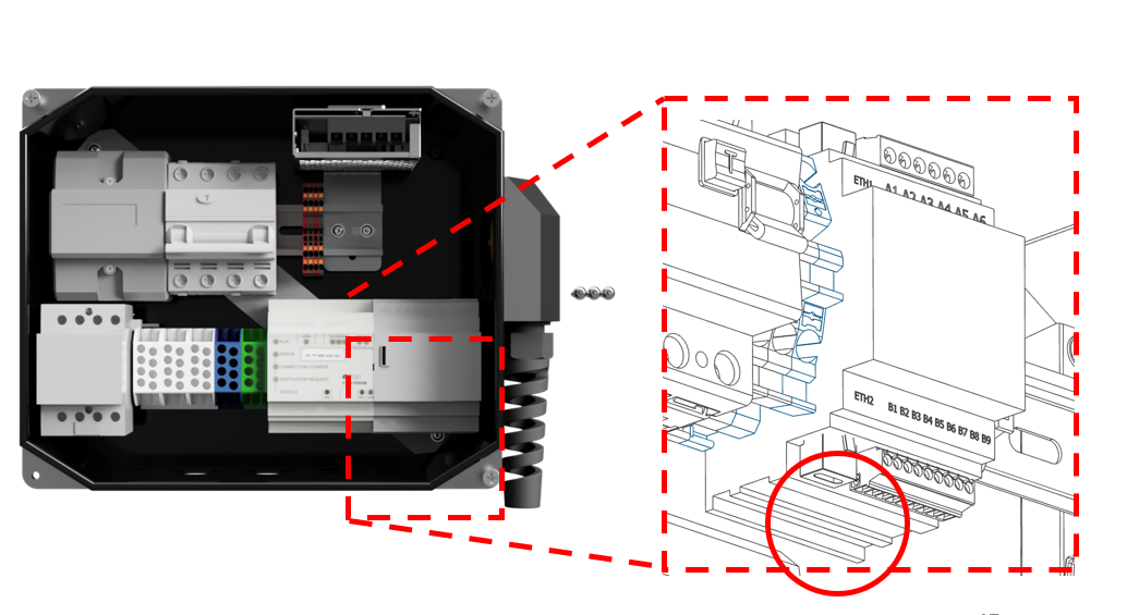
If Wallbox One contains SmartSystem, connect Ethernet to ETH2. Feed FTP CAT cable, minimum Cat5e, through the gland and fit RJ45. Check manually fitted connectors at both ends using an Ethernet cable tester according to its manufacturer's instructions.
Connecting CAT cable to RJ45:
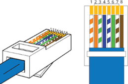
1 white/orange; 5 white/blue
2 orange; 6 green
3 white/green; 7 white/brown
4 blue; 8 brown
After a successful Ethernet test, connect RJ45 to ETH2 on the control unit's bottom, as illustrated. Do not connect to ETH1 at the top.
5.6 Installing the Type 2 charging cable
For a cable-equipped Wallbox One, connect the Type 2 charging cable if it is not already installed.
Only a qualified electrician may perform installation. Switch off the incoming Wallbox One cable's breaker in the distribution board first. Follow the installation instructions.
Charging cable conductor insulation uses these colours:
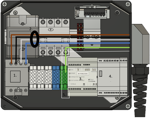
L1 brown, L2 black, L3 grey, N blue, charging PE green/yellow, CP white
- Contactor
- Residual-current sensor
- Communications module: EV module
- SmartSystem
- CP — white conductor
Installation procedure:
- Disconnect Wallbox One from power and remove the front cover by undoing four screws.
- Install cable glands using four screws and four nuts
- Feed the charging cable's end without the TYPE 2 plug through the glands on either side, leaving enough length to reach terminals with spare length.
- Start by connecting the green/yellow PE conductor to its terminal as illustrated.
- Pass L1, L2, L3 and N through the residual-current sensor coil.
- Connect L1, L2, L3 and N to the contactor terminals and tighten using a PH screwdriver.
- Insert the charging cable's CP signal conductor into slot C1 of the communication unit and tighten with a flat-head screwdriver.
- Check that all charging cable conductors are correctly connected and appropriately tightened.
- After checking connections, secure the charging cable using its gland.
- Refit the front panel.
After these installation steps, the charging cable is ready for charging.
6. Commissioning the charging station
Before switching on the incoming cable's circuit breaker, check for short circuits between conductors using a multimeter.
6.1 Initial startup
Switch on the wallbox's internal RCBO/MCB and close the front panel. Switch on the distribution board's switch/breaker. If SmartSystem is external, power it too. Wallbox One starts with factory defaults; adjust charging power to the available upstream breaker capacity.
Set charging power in SmartSystem before the first charging session.
7. Troubleshooting
7.1 Possible problems and solutions
|
Status |
Error |
Solution |
|
The charging station did not start or is not working correctly |
The input phase sequence L1, L2, L3 (U, V, W) is incorrect. |
Check the phase sequence. |
|
Input conductors are not correctly fitted in terminals. |
Check conductor fastening and tighten connections. | |
|
The display shows: Circuit breaker error |
The station's residual-current device/circuit breaker has tripped. |
Check the residual-current device/circuit breaker inside the station. |
|
The display does not work although the station's circuit breaker is on |
SmartSystem fault. |
Check SmartSystem power and correct operation. |
|
The display shows HALT |
The system is updating. |
Wait for the update to finish. |
|
The station is incorrectly configured in SmartSystem; the display address differs from the configured address. |
Adjust the SmartSystem configuration. |
7.2 Restarting the charging station
Disconnect Wallbox One from power for 10 seconds, then switch it on again
Text © AgeVolt Slovakia, s. r. o. 2024
Image © AgeVolt Slovakia, s. r. o. 2024
This manual is protected by copyright. Use without the creator's consent is prohibited. Copying, including partial copying, requires their permission.